

Software we built and use ourselves
One tag list in, print-ready loop sheets and wiring schedules out
Barmaan's instrumentation team types the tag table once — instrument, service, junction box — and this tool assigns every channel and terminal, then draws the ISA loop sheets and the JB/panel wiring schedules from that single record. Nothing is redrawn by hand and nothing is stored twice: the sheets are recomputed from the tag list on every render.
The 3D view and the numbers below run on a real, seeded project — a real DCS marshalling cabinet — not placeholder data.
Who this is for
Four people, four different questions
Instrumentation / EPC engineer
Can you turn our tag list into loop sheets and wiring schedules we can issue to a vendor?
Yes — one tag table produces both: an ISA 5.4 loop sheet per instrument and the JB/panel interconnection schedules, from the same engine.
Panel shop / commissioning technician
Which terminal and channel does each wire actually land on?
Every channel's card-side and strip terminal numbers are computed from the project's terminal layout and printed on the sheet — no separate spreadsheet to keep in sync.
Procurement / expediting
What hardware does a tag like "FT-101" actually mean for the BOM?
The equipment manifest below matches each tag's ISA letters to a real manufacturer model, and marks plainly which model the project documents confirm and which is a standard assumption.
A company that wants the same system
Do you build this kind of engineering software for other companies too?
Yes — this designer is one example of the software department's in-house engineering work. Ask for details with the form below.
What is actually inside
One project record, 7 tabs
A loop-diagram project stores only what an engineer decided — the tag table, the project settings, and any channel a person pinned by hand. Everything else on the tabs below — channels, terminals, cable names, drawing numbers — is computed by the same engine on every render, so the rack view, the sheets and the termination tables can never disagree.
Rack
The remote-I/O rack: how many cards it carries, how many channels each, and how many are already used.
Tag table
Every field instrument as one row — tag, service, calibrated range, junction box — the inventory the whole design is built from.
Loop sheet
One ISA 5.4 instrument-loop sheet per tag, generated as a print-ready A4 drawing: field device → junction box → marshalling cabinet → I/O card.
Wiring schedules
JB and panel interconnection sheets — the terminal rail, the trunk-cable core and the card side, one sheet per junction box or panel.
3D view
The rack and cabinet in three dimensions with camera presets, textured with real manufacturer product photos, not renders.
Terminals
Every channel's card-side and strip-side terminal numbers, computed from the project's terminal layout (paired or grouped).
Settings
Project scalars: company and project name, drawing prefix and revision, cabinet name, cable and terminal numbering rules.
The 3D signal path, live
Click a field instrument and follow its wire to the card
A real slice of a seeded project — sixteen of a real project's tags across three junction boxes — run through the same runLoopDesign engine the admin studio uses. Drag to rotate, click an instrument or a card slot, and its junction box, trunk cable, terminal and channel open beside it.
The signal path — click an instrument
A real slice of a seeded SCADA wiring project: field instrument → junction box → main cable → marshalling cabinet → input card. Click an instrument or a card to light up its whole path.
Right-drag: rotate · left-drag: pan · wheel: zoom · click: select a loop
Real numbers, sample project
Read off DCS Marshalling Cabinet — Field Signal Wiring (sample slice)
- Instruments shown
- 16
- Junction boxes
- 3
- Cards in use
- 3
- Channels used / capacity
- 16/88
Real hardware behind the drawing
A photo manifest, not a render
Every card, cabinet, junction box and transmitter in the 3D view above is a real manufacturer product photo — Siemens, Rittal, Pepperl+Fuchs, Emerson/Rosemount and Endress+Hauser data sheets — not a stock illustration.
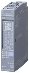
Siemens
SIMATIC ET 200SP AI 8xI 2-/4-wire ST
Confirmed by the project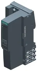
Siemens
SIMATIC ET 200SP IM 155-6 PN ST
Confirmed by the project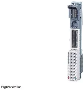
Siemens
SIMATIC ET 200SP BaseUnit BU15-P16+A0+2D
Confirmed by the project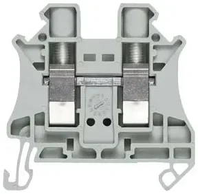
Siemens
8WH screw terminal 2.5 mm² (terminal boards TB1…TB13)
Standard assumption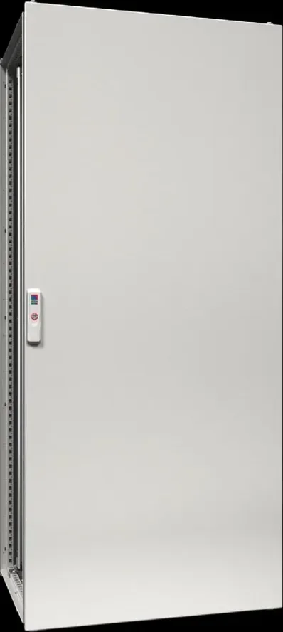
Rittal
VX25 baying enclosure 800 × 2000 × 600 mm (DCS marshalling cabinet)
Standard assumption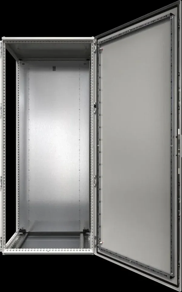
Rittal
VX25 baying enclosure — door open
Standard assumption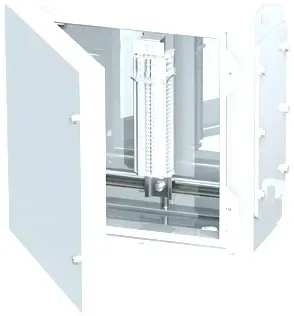
Pepperl+Fuchs
SR.T* Ex e / Ex i terminal & junction box, stainless steel 316L (JB1…JB3)
Standard assumption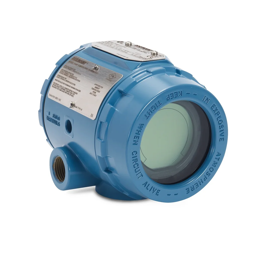
Emerson / Rosemount
Rosemount 3144P temperature transmitter (TT loops)
Standard assumption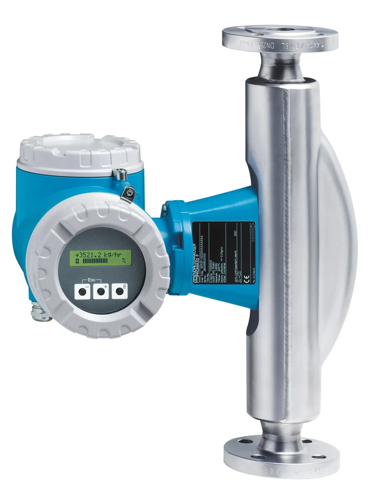
Endress+Hauser
Proline Promass 80F Coriolis flowmeter (FT loops)
Standard assumptionWant this for your project
We can wire your project's loop diagram the same way
Send us your tag list and junction-box layout; we return print-ready loop sheets and wiring schedules generated by this same engine, not redrawn by hand.